Using CANopen to Simplify a S7-1200 Control System
- Justin Stewart

- Oct 13, 2022
- 14 min read
CANopen is a communication protocol and device profile specification for embedded systems used in automation. The protocol was developed for embedded networking applications, such as in-vehicle networks. The CANopen umbrella covers a network programming framework, device descriptions, interface definitions and application profiles. CANopen provides a protocol which standardizes communication between devices and applications from different manufacturers. It has been used in a wide range of industries, with highlights in automation and motion applications.

Hardware
Ixxat CM CANopen module - PN: 021620-B
Siemens S7-1214C - PN: 6ES7214-1AG40-0XB0
Grayhill 3K Series Keypad - PN: 3K106-2RN3AG
RoboteQ DC Motor Controller - PN: SDC2160
Links to product pages above...

The Network
The S7-1200 is connected through the CAN bus to 4 external devices with the following node addresses.
Node ID | Label | Device |
127 | Master | CM CANopen Module |
10 | OP1 | Grayhill 3K106 Keypad |
20 | OP2 | Grayhill 3K106 Keypad |
30 | MC1 | RoboteQ Motor Controller |
40 | MC2 | RoboteQ Motor Controller |
Setting up the CM CANopen master module
Here's a few files you'll need to setup the CANopen network and devices...
Install the EDS files into the CM CANopen configuration studio


When importing a device to the configuration studio use the Tools→Manage Catalog menu. Then the Device Catalog Management window opens and using the Edit→Import Device or the command button you can then open the browser window to select the EDS file you would like to import.
The two files in this instance you need to import are as follows...

After the process is finished you'll end up with two new CANopen devices in the catalog list...


Create the CANopen network configuration
To start a new project go to File→New or use the Ctrl+N keyboard shortcut.

Update the project path to be wherever you want the file stored and name the file. Then select the Ixxat CM CANopen module manager device in the project parameters (there's only one to select). At this point unless you know you have other parameters for the node-ID and process image sizes just leave the defaults as is. Now your Project Explorer tool window will have the Manager divice added to the project as shown below.

We need to add our slave devices from the Device Catalog tool window underneath the Project Explorer tool window. The Grayhill 3K Series Keypad will be listed under the 'CiA 401 - Generic I/O Modules' navigation pane. To add the device, select the device that shall be added to the network description and drag it to the Project Explorer window and drop it there.

The Device Properties pop-up will show once you've dropped the device into the Project Explorer tool window. Name the device, enter the Node-ID that matches the device, and select the 'Slaves' group. The description will help identify the device in the network and is an optional entry. The Node-ID is the manufacture assigned or user assigned node number of the device that will be used by the network to identify the device. In the case of the Grayhill 3K keypad, this will be by default 0x0A or 10 as shown in the Grayhill CANopen Manual Engineering Specification dated 12/14/2016 rev. C. This can be found in the CANopen Project Files.zip file towards the beginning of this blog.

For this project another 3K keypad was added at node 0x14 or 20 using the step described above.
The RoboteQ DC Motor Controller will be listed under the 'CiA 402 - Drives and Motion Control' navigation pane. To add the device, select the device that shall be added to the network description and drag it to the Project Explorer window and drop it there.

The Device Properties pop-up will show once you've dropped the device into the Project Explorer tool window. Name the device, enter the Node-ID that matches the device, and select the 'Slaves' group. The description will help identify the device in the network and is an optional entry. The Node-ID is the manufacture assigned or user assigned node number of the device that will be used by the network to identify the device. In the case of the RoboteQ DC Motor Controller, this will be setup in the Roborun+ Motor Control Utility. This can be found in the CANopen Project Files.zip file towards the beginning of this blog.

For this project another DC Motor Controller was added at node 0x28 or 40 using the step described above.
The Project Explorer is now setup to identify all of the devices in the CANopen network that we will use in this project.

Network Management Configuration
The network management page supports configuration of the NMT functionality of the managing device.

NMT Startup
The NMT startup configuration specifies the behavior of managing and self-starting devices in the network. The configuration corresponds to object 1F80h NMT startup of these devices. All bits except bit 0 NMT master may be configured. Bit 0 is read-only as the active manager can not be changed after the project was created.

Bit 0 must be set
Bit 1 should be set There is no difference between set / not set from the view of the PLC application. Set bit guarantees that the Manager is operational when a slave is set to operational.
Slave Assignment
The slave assignment configuration specifies how the manager will treat its slave devices. Most options are related to network startup and configuration verification which also takes place during startup.

Bit 0 must be set otherwise the device – if connected – is managed as an unexpected device that should not be connected
Bit 2 should be set so the Manager automatically retries to find and configure a slave device after an error control event Note: A slave that has not been configured successfully will not be set to operational
Bit 7 should not be set if a slave is preconfigured by its own tool Note: If slave device is preconfigured by its own tool => the EDS must be adjusted to this configuration => Bit 7 must not be set Otherwise, Bit 7 should be set if a slave can save a configuration
Additional Manager Objects
Boot Time (ms)
Is not relevant for the CM CANopen
NMT Inhibit Time
If there are problems with the startup of the CANopen network set it to 100
Note: Some devices run in a receive queue overrun when there is a burst of NMT commands.
Final Settings

Error Control Configuration
The Error Control Configuration page implements user interface controls enabling the user to configure the NMT error control functionality and dependencies of the devices within the network. Depending on the functionality implemented by the devices, the configuration of either heartbeat or node guarding functionality is supported.

Error Control Configuration
The error control list supports the parameterization of the individual error control objects implemented by the devices in the network. If a device does not support a particular functionality the corresponding entry will be marked as not available (N/A).

The CANopen specifications state that heartbeat and node guarding must not be concurrently used for the same device. Thus CM CANopen Configuration Studio will require the user to deactivate one of the mechanisms if an entered value would cause both mechanisms to be activated.
The consumer heartbeat time(s) (object 1016h) is configured in an extended context menu. The menu is opened by clicking the ellipsis button which appears when the consumer heartbeat cell is selected. The list contains as many entries as supported by the selected device.

Slaves should be controlled by the Manager either by consuming its heartbeat or by guarding, otherwise:
The Manager will not detect if a slave has been disconnected after successful configuration.
If a slave has changed is CANopen NMT state from operational to not not operation due to an error
The status of a slave device read by Get Node & Network Status does not display the current CANopen NMT state
Global Default Values
The default values are used for configuration operations on the error control page.
Error Control Timeout
Used to preset object 1017h Producer heartbeat time respectively object 100Ch Guard time on the CANopen slave. It is also used to set the Guard time field of the sub-index in object 1F81h NMT slave assignment on the NMT master corresponding to the node-ID of the CANopen slave. If the Set command of the tool bar is executed the value is written to all devices as either producer heartbeat time or guard time. As CANopen specifies that only either heartbeat or node guarding may be used to monitor a CANopen device, CM CANopen Configuration Studio will first configure the heartbeat functionality. Only if heartbeat is not supported by a device CM CANopen Configuration Studio will configure node guarding.
Node Guarding Retry Factor
Used as an initial default for object 100Dh Life time factor on the CANopen slave and the Retry factor field in the sub-indices in object 1F81h NMT slave assignment on the NMT master if guarding is activated.
Ratio Consumer Heartbeat Time to Producer Time
Used to calculate the initial value for the consumer heartbeat time based on the producer heartbeat time configured for the CANopen device to be monitored.
Final Settings
Node | Producer Time | Node-ID | Consumer Time |
10 | 0 | N/A | |
20 | 0 | N/A | |
30 | 0 | 127 | 1000 |
40 | 0 | 127 | 1000 |
127 | 500 | 30 | 750 |
| | 40 | 750 |


Application Objects
The specification which of the process data implemented by CANopen slave devices in the network are mapped to the process image on the CANopen manager device is performed on the Application Objects workspace page.

Application Objects List
The application objects list displays all mappable objects on the CANopen slave devices in the network in a tree list view. The application objects are sorted according to the node-ID of the device, their object index, and finally the sub-index of the entry.

For the Grayhill 3K keypads, we will be mapping all of the objects to the process image. To do this mark the 'Mapped' checkbox under Node-ID: 10 and 20 for all objects. You may have to expand the tree structure to display the checkbox.

For the RoboteQ DC Motor Controllers, we will be mapping the first 4 TPDO and RPDO objects to the process image. To do this mark the 'Mapped' checkbox under Node-ID: 30 and 40 for all desired objects. You may have to expand the tree structure to display the checkbox.


Additional Global Objects
The global value section allows to configure parameters which apply to the PDO mapping and PDO communication in general.
Communication Cycle Period
Specifies with which interval a SYNC producer shall transmit a SYNC message. The field corresponds to object 1006h Communication cycle period of the CANopen manager in the CM CANopen module.
Note: The value entered in the text field uses one millisecond as time basis, and not one micro second as specified in the CANopen application layer and communication profile specification CiA 301.
SYNC Producer
The combo box allows to select an alternative producer of the CANopen synchronization message from a list of all devices in the network that support SYNC producer functionality.
Process Image Size (IN/OUT)
Define the upper limit for the process image on the CM CANopen module in bytes that may be allocated by network variables. The currently allocated part of the process image is indicated in the toolbar.
Final Settings

Calculating Process Configuration
To verify the configuration of the PDO communication based on this object selection, navigate to the Build menu and select Calculate Configuration. This creates a structure with new network variables in the process image on the CM CANopen module.


Process Image
The process image page displays the process image of the CANopen manager that is created by the configuration.

Process Image List
The process image list displays all objects that were mapped to the process image of the CANopen manager. Objects that are highlighted with a alternate background color have been added to the list of objects selected for inclusion into the process image after the last calculation of the PDO connections and the process image layout. The Address column for those objects will remain empty until the project is recalculated.

The final Process Image should look like the following...

Downloading the Configuration to the CM CANopen Module
Before the configuration can be downloaded to the CM CANopen module, the configuration data for the CANopen network has to be generated. This is performed by selecting Generate Configuration from the Build menu or the corresponding toolbar button. We save the generated configuration data into the same folder as our network project.
Interface Configuration
Before starting the download it is required to specify the interface that will be used to transfer the configuration data to the CM CANopen module. This may be performed via selecting the Network→Interface Configuration menu item or the corresponding toolbar button or directly from within the Download dialog via the Configure... button.
In this case the PC running CM CANopen Configuration Studio is connected to the CM CANopen module via a USB cable. If several CM CANopen module devices are connected to the host PC, we need to select the module we want to download the configuration to.
Download of Configuration Data
The Download dialog is used to download network configuration data to a CM CANopen module. The dialog is available via the Network→Download menu item or the corresponding toolbar button. CM CANopen Configuration Studio supports two download interfaces. CAN/CANopen and USB. See the help page on network interface configuration for information about the CAN/CANopen interface.

The desired download interface may be selected via the Download Interface combo box. The Configure button opens the Interface Configuration dialog of the currently selected interface. The file that shall be downloaded is selected via the ellipsis button. CM CANopen Configuration Studio currently supports *.cmcdc files.
The download is controlled by the buttons at the bottom of the dialog. Download starts the download of the selected file using the selected interface. While the download is running the progress bar will indicate the current status. A running download may be aborted by means of the abort button.
After the download, a message box confirms the successful completion of the procedure. Click OK and then Close to close the dialog.
Analysis of the LEDs
RUN LED: ON <–> ERR LED: OFF
CAN communication is running
All CANopen slaves that are expected are connected and have been configured successfully
RUN LED: Flashing <–> ERR LED: Single flash
No CAN communication
Reasons:
Disconnected
Connected devices do not communicate with CAN
CAN controller of all connected devices have reached warning level set and do not confirm a received CAN message.
RUN LED: Flashing <–> ERR LED: ON
CANopen network bus off
Reasons:
Incorrect wiring
Devices run with different CAN baudrates
RUN LED: ON <–> ERR LED: Double Flash
Error control event
Reasons:
Missing CANopen slave
Heartbeat event of a CANopen slave
The configuration of a CANopen slave has failed
A CANopen device is present that is not configured as slave
Setting up the S7-1200 Program
Once the CM CANopen module has been programmed you're halfway to getting the communications setup for the CANopen network to work. The program application has been included for v14 of TIA Portal. This will allow you to get this example up and running and give you a basic understanding of the program quicker than setting everything up from scratch.
Here you should open the TIA Portal Demo that was included with the blog. The rest of this will assume that you are using this file and will directly correlate with naming conventions and file layouts using this project file.
Install the Hardware Support Package (HSP) into TIA Portal
Go to Options→Support packages. This will open the Detailed information window with the 'Installation of support packages' page already open.

Then click on the 'Add from file system' button to open the windows file browser to select the HSP you are trying to install. Once the HSP is opened it will be added to the list you will see it listed under local support packages, but in the 'Installed' column it will be listed as No.

Select the CANopen HSP checkbox and click on the 'Install' button. In the TIA Portal a message requesting you to close all instances is displayed. Click "OK"

You can only continue with the installation when all instances of TIA Portal are closed. Until then, the "Continue" button as shown is not enabled. Close the "Detailed information" dialog and the table with the list of Support Packages. Also close all the open windows of the TIA Portal except for the "Support Package Installation" dialog. This enables the "Continue" button. Click "Continue" to start the installation.

At the end of the installation a message is displayed indicating that the installation has been completed successfully. Click the "Finish" button and restart TIA Portal.

Setup the CM CANopen module in the Device Manager
After you add the CM CANopen HSP into TIA Portal you can install it and modify it like any other I/O module in the Device Manager. The settings are as follows:
Node number = 127
Buadrate = 250
Input size = 70
Output size = 88
The CANopen Manager auto configuration checkbox must remain unchecked.

Setup the Process Image Input and Output Data Type
The process image structure that you created when setting up the CM CANopen module will be copied into the PIInput and PIOutput data types to be used across the program. When setting up the structure be sure to copy the data type size correctly or the data map will be wrong and the data will not end up in the correct place in the program.

Input Map (PIInput)


Output Map (PIOutput)


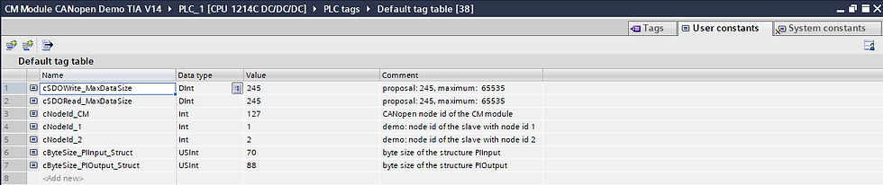
Setup the Data Structure "cByteSize" User Constants
The user constants in the 'Default Tag Table' should match the size of the CM CANopen process structure configuration.
cNodeId_CM = 127 (Node ID)
cByteSize_PIInput_Struct = 70 (Bytes)
cByteSize_PIOutput_Struct = 88 (Bytes)
Change the logic in the Input and Output Program Blocks
The process image structure that you created when setting up the CM CANopen module was copied into the PIInput and PIOutput data types to be used across the program. When setting up the program blocks to copy the data into the PLC tags for program use, be sure to do a byte swap on the 16 bit and 32 bit values so they show up in the PLC tags correctly.

UpdatePIInData_PLC

UpdatePIOutData_CM

Grayhill 3K106 Device Setup
The keypad comes with a few default values to note:
Node ID = 10 (0x0A)
Heartbeat = 0
Baud Rate = 250 kbps

Change Node ID
Changing the NodeID requires the use of the CANopen Layer Setting Services (LSS DS-305)
Follow the steps outlined below:
1. Put the device in STOP mode by sending the following
ID = 000h, LEN=2, Data = {02h, 00h}
2. Send the Switch State Confide.
ID = 7E5h, LEN=8, Data = {04h 01h 00h 00h00h00h00h 00h}
3. Send the Change Node ID command
ID = 7E5h, LEN=8, Data = {11h 14h 00h 00h00h00h00h 00h}
The 2nd byte holds the value of the new node ID
This example sets it to 20 decimal (0x14 hex)
4. Send the command to store the new setting in eeprom
ID= 7E5h LEN= 8 Data = {17h 00h 00h00h00h00h00h00h}
Note: The node address was setup with CANopen Magic Professional using the Layer Setting Services (LSS) support built into the software with the PEAK-System Technik PCAN-USB hardware adapter SKU# IPEH-002021.
RoboteQ Motor Controller Setup
To configure communication parameters via the RoborunPlus PC utility, your controller must be connected to a PC via an RS232/RS485/TCP/USB port. Use the CAN menu in the Configuration tab in order to enable the CANopen mode.

Additionally, the utility can be used to configure the following parameters:
Node ID
Bit rate
Heartbeat (ms)
Autostart
TPDO Enable and Send rate

For the current example, copy the settings in the figure above for the RoboteQ devices. MC2 will require the Node ID to be set to 40.
CAN Mode
Four CAN operating modes are available on Roboteq controllers:
RawCAN
MiniCAN
CANopen
RoboCAN
RawCAN is a low-level operating mode giving total read and write access to CAN frames. It is recommended for use in low data rate systems that do not obey to any specific standard. CAN frames are typically built and decoded using the MicroBasic scripting language.
MiniCAN is greatly simplified subset of CANopen, allowing, within limits, the integration of the controller into an existing CANopen network. This mode requires MicroBasic scripting to prepare and use the CAN data.
CANopen is the full Standard from CAN in Automation (CIA), based on the DS402 specification. It is the mode to use if full compliance with the CANopen standard is a primary requisite.
RoboCAN is a Roboteq proprietary meshed networking scheme allowing multiple Roboteq devices to operate together as a single system. This protocol is extremely simple and lean, yet practically limitless in its abilities. It is the preferred protocol to use by users who just wish to make multiple controllers work together with the minimal effort.
Bit Rate
The CAN bus supports bit rates ranging from 10Kbps to 1Mbps. The default rate used in
the current CANopen implementation is set to 250kbps. Valid bit rates supported by the
controller are:
1000K
800K
500K
250K
125K
Node ID
Every CANopen network device must have a unique Node ID, between 1 and 127. The
value of 0 is used for broadcast messaging and cannot be assigned to a network node.
Listen Node ID
Filters to accept only packets sent by a specific node.
Heartbeat
A heartbeat message is sent to the bus in millisecond intervals, according to the value of the
object 0x1017. Heartbeats are useful for detecting the presence or absence of a node on the
network and determining the NMT state. The default value is set to 0ms (deactivated).
CHB Lost Action
The consumer heartbeat monitors if the producer heartbeat device is active on the
network. Up to four devices can be monitored. The consumer heartbeat lost action can
be configured through the Roborun+, by choosing either Safety Stop or Emergency Stop.
When the consumer heartbeat is lost the watchdog is considered expired.
MiniCAN Send Rate (ms)
Period at which data frames are sent by the controller. Frames are structured as standard CANopen Transmit Process Data Objects (TPDOs). Transmission can be disabled by entering a value of 0.
CANopen TPDO Send Rate
Sets the send rate for each of the 4 TPDOs when CANOpen is enabled.
CANopen Transmission Type

See the CANBus Networking Manual for the RoboteQ controler for more information.
CANopen Autostart
When AutoStart is enabled, the controller automatically enters the Operational mode of
the NMT state machine of the CANopen. The controller AutoStart is disabled by default.
Disabling the parameter, will prevent the controller from entering operational state
automatically, after the reset occurs. When Autostart is disabled, after power on or reset,
the NMT state will not automatically do the transition and will remain to pre-operational.
DS402 FSA
Enables or disables the PDS Finite State Automation (FSA), as dictated in DS402 specification.
Final thoughts
With any luck the CANopen network will have basic communications setup to get all the device data into the S7-1200 PLC. Once this is verified then the real challenge begins and the programmer must make the modifications to make the control system work. This blog has covered all the topics to get the CANopen system communications setup and give the reader a basic understanding of the process used to get all of the devices on the CANopen network sending data to and from the PLC. With this foundation of knowledge the reader can open the automation catalog to those devices that use the CANopen protocol with the S7-1200 CM CANopen module's help.
Did you like this post?


Comments